 A....
A.... B....
B....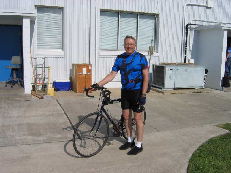 C....
C.... D....
D.... E1...
E1...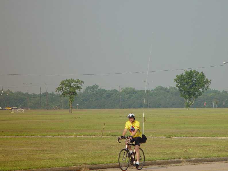 E2(High
Res)
E2(High
Res)
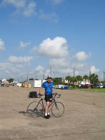
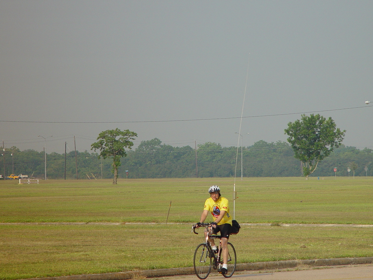
This is a discussion of a bicycle mobile
for HF running 100 watts. The transceiver is a Yaesu FT-857 which
weighs about 4 pounds. The console of the transceiver is separated
from the main transceiver body and is mounted on the handle bars.
The antenna is home-brew and the rig is powered by a 12 Ah, gel cell which
gives at least 2 hours of normal operation in between charges. The gel
cell weighs about 8 pounds.
A....B....C....D....E1...E2(High
Res)
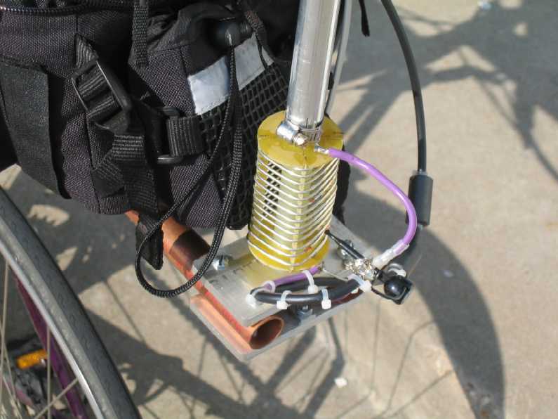
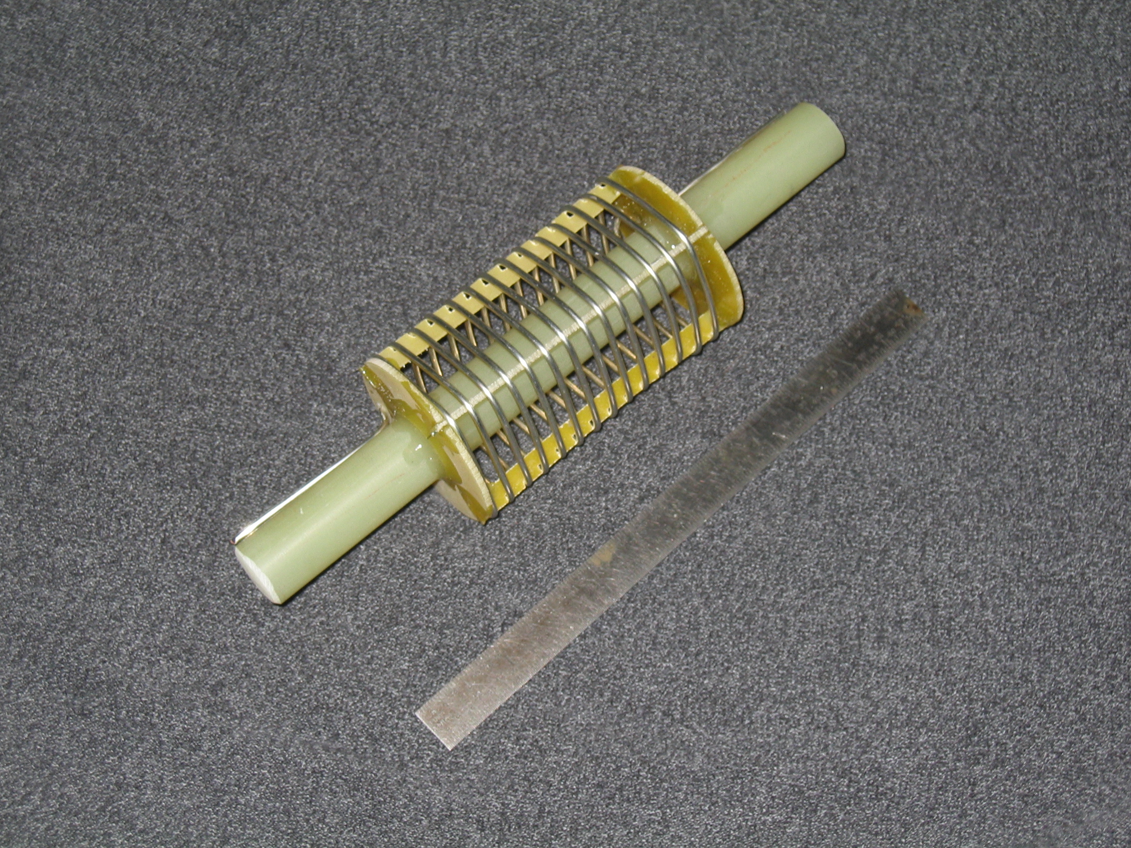
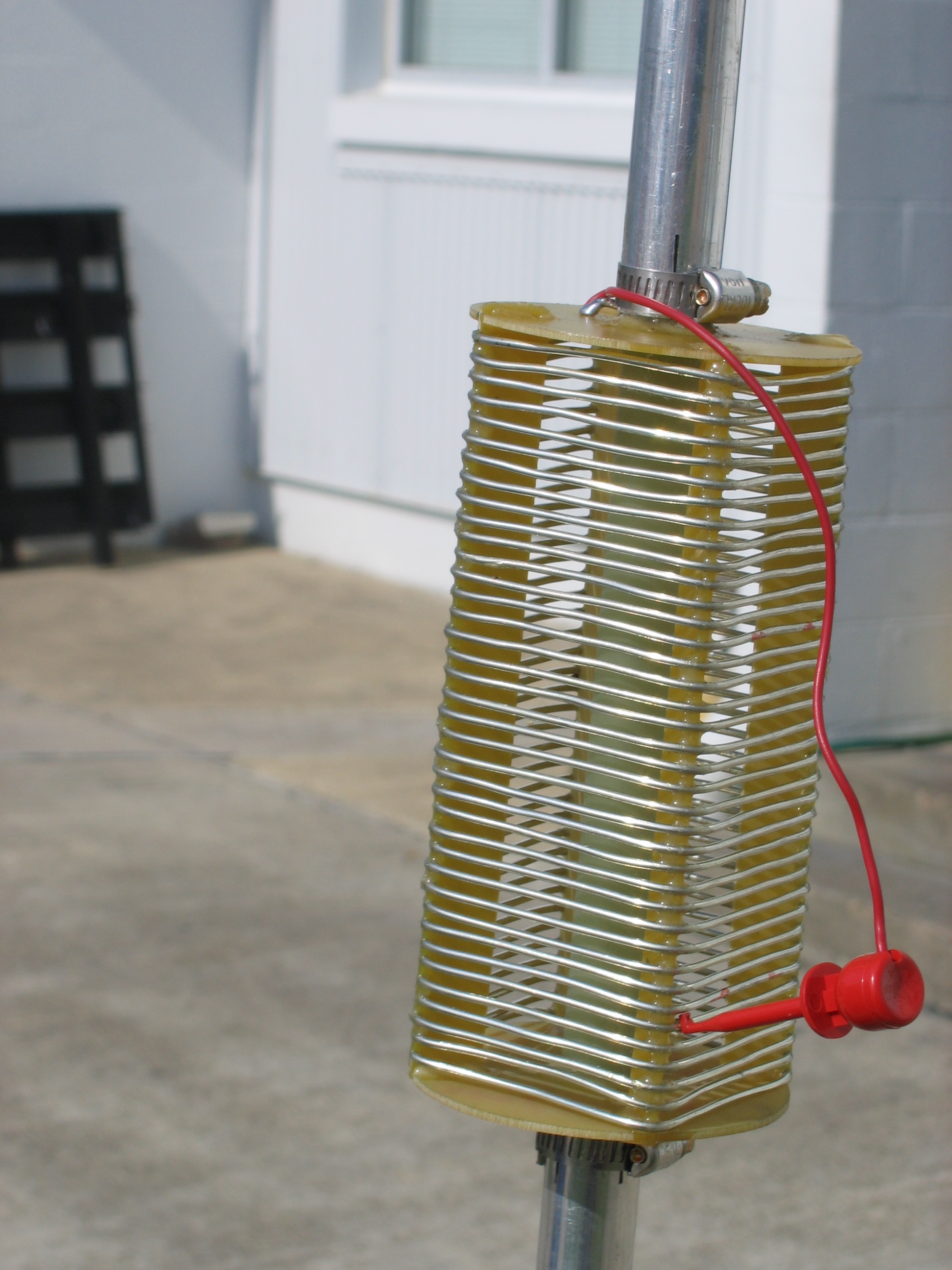
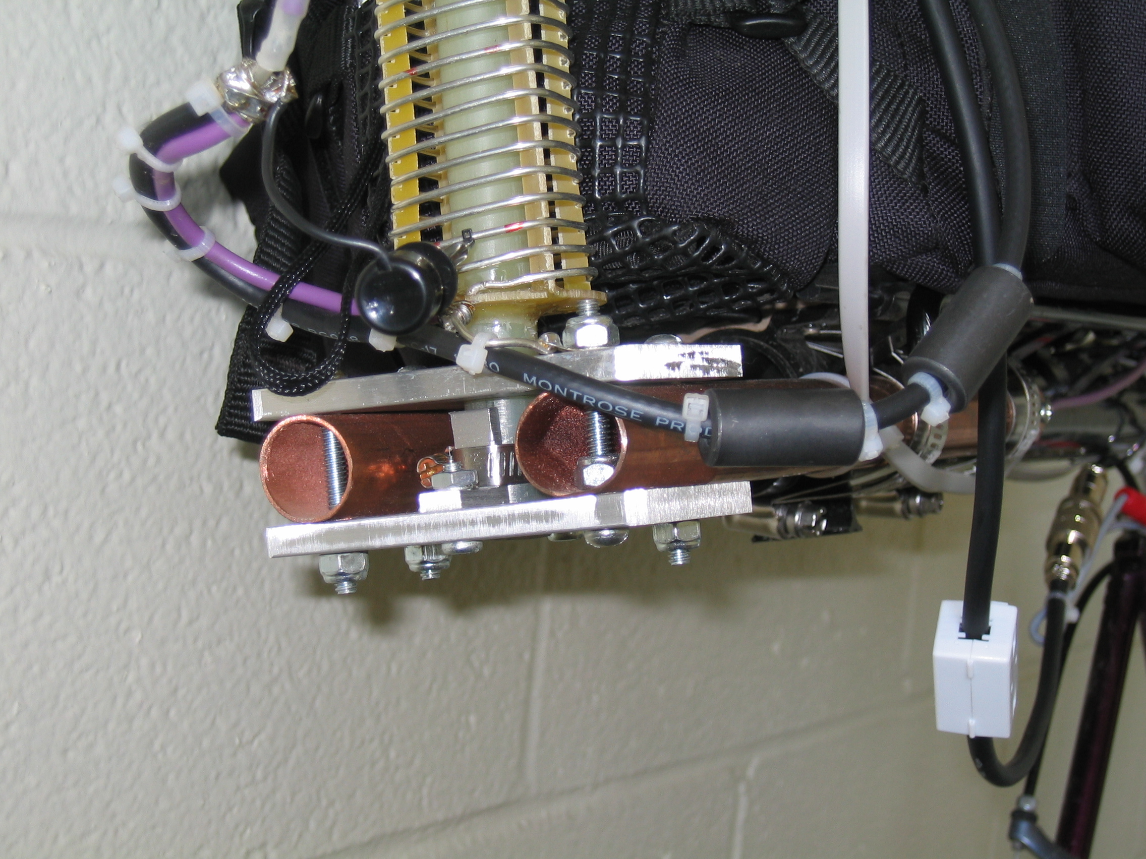
Pictures F, G, and H show details of the loading coil. The ruler is 6 inches long. The coil is made from PC board material with the copper stripped off. The center rod is a 5/8 inch diameter, fiber glass rod which is the main structural element of the coil. The coil supports were stacked together with double sided tape, marked for the correct coil pitch, and slotted altogether with a band saw. They were then separated and installed as shown. Figure G shows the finished form held together with epoxy glue, and figure H shows the wire on the form. A small drop of epoxy glue was applied to the coil at each slot on the form. The finished product is very sturdy and robust. Figures I and J show the main tuning coil. This coil measures about 33 uH with an unloaded Q of about 450 at 7 mHz. Photos K, L, and M show the details of the mount.
 F....
F....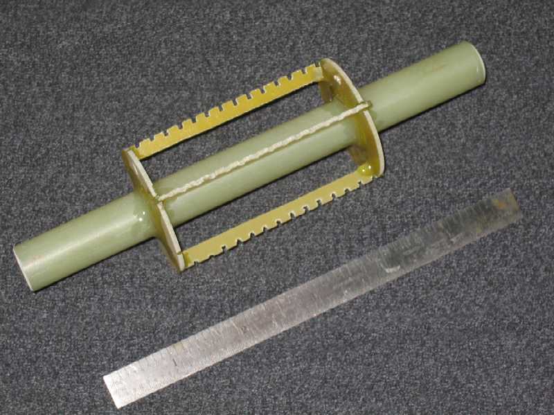 G....
G....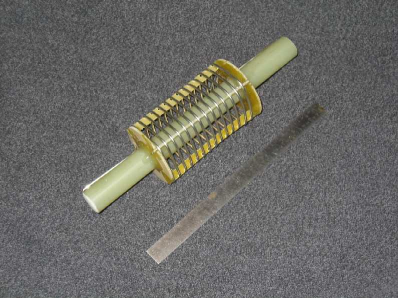 H
(High
Res)..
H
(High
Res)..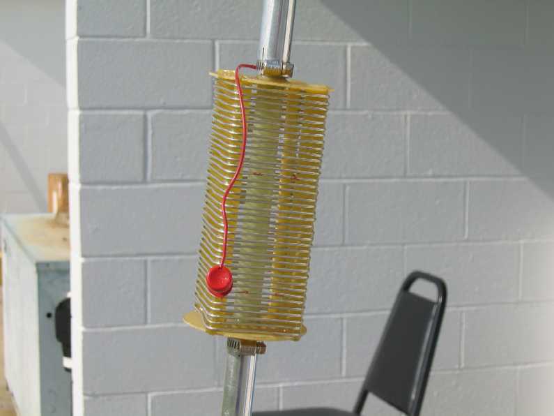 I....
I....
 J
(High
Res)..
J
(High
Res)..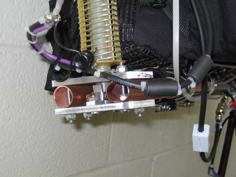 K(High
Res)....
K(High
Res)....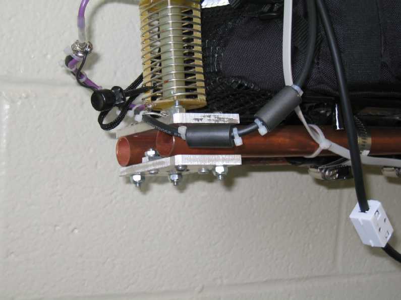 L....
L....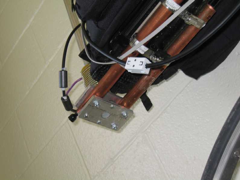 M
M
Photo N show the transceiver and the battery
sitting in the back pack. Photo O shows the battery removed
from the back pack. The battery is charged between rides by applying
about 14 volts current limited to 300 mA for several hours. I have
used this arrangement to commute to work and, it has worked well.
 N....
N....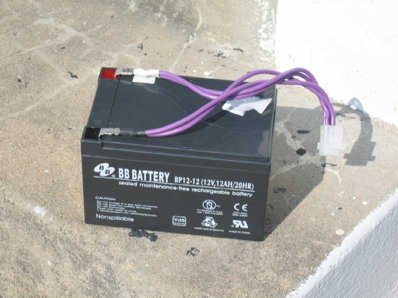 O
O
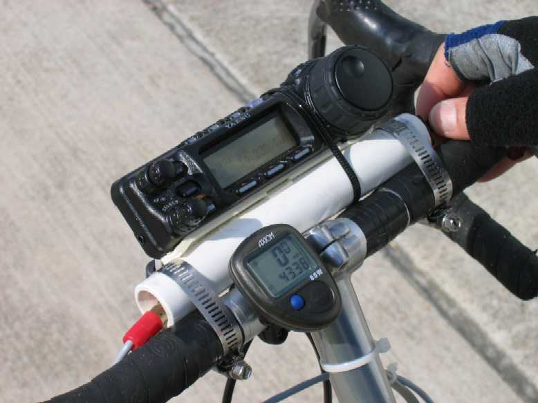
The console of the FT-857 is mounted to a 1" diameter
piece of PVC pipe using some double sided sticky tape and a single tie
wrap. A toggle switch is epoxied into the right opening of the pipe
for transmit control and the connection for it comes out the left side
of the pipe. The pipe is held to the handle bars with hose clamps.
Photos P and Q show those details. Photo R shows
the transmit switch. It is a SPST toggle that I can work with my
thumb without removing my hands from the handle bars. I can tune
the radio with my thumb in a similar manner.
. P....
P....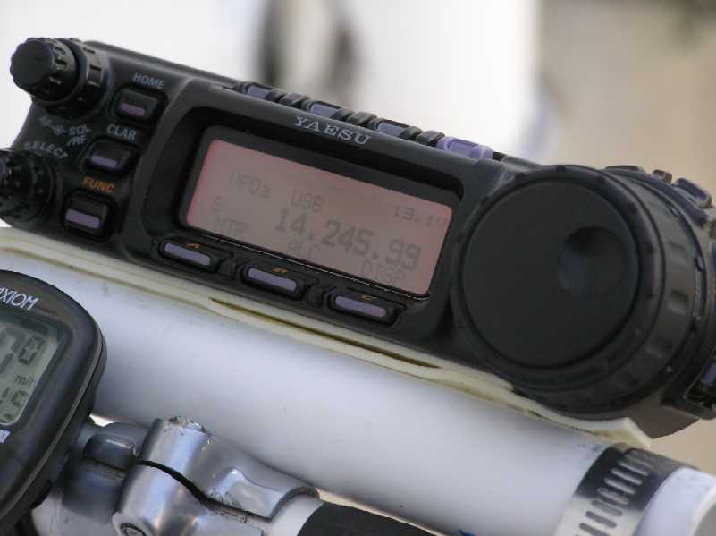 Q....
Q....![]() R
R
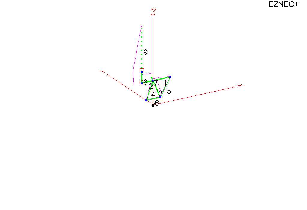
The antenna has a 22 inch extension between the loading coil and the tuning coil. The stinger is 96 inches long with a 6 inch adapter between it and the loading coil. RF exposure was checked using the conventional formulas and was found to be safe. Figures S and T show the 20 meter, EZNEC modeling that I did on the installation.
 S....
S....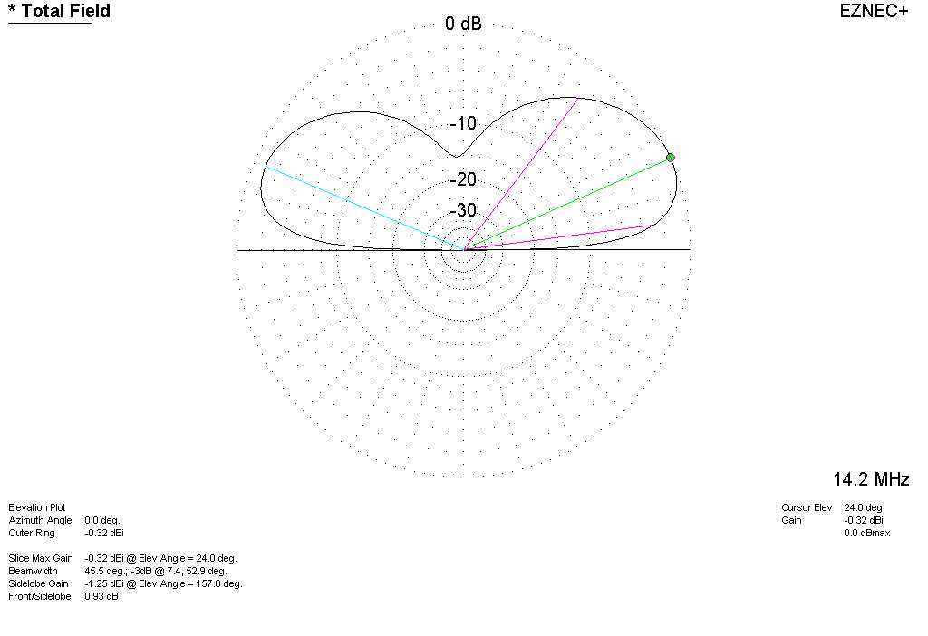 T
T