 A..HR..
 B..HR..
 C..HR..
 D..
D..
Since I travel alot, I decided to build a small, relative light weight amplifier. Small and light weight means that a 600-watt continuous duty amplifier was out of the question. The amplifier described here is for intermittent continuous duty modes such as CW and SSB. The specification of the completed amplifier are listed below:
Specifications
Bands of operation:
80, 40, 30, 20, 17, 15, 12, and 10 meters
AC Input:
120 V / 240 V (switchable)
Peak Output Power:
600 Watts
Drive power:
10 Watts
Protection:
Over Drive
Over Temperature
High SWR
Output Filters:
Included
Power Supply:
Non-regulated linear (included)
Cooling:
Forced air with a temperature controlled crossflow blower
Aluminum heat sink with copper spreader
Size:
12 inches x 12 inches x 5 inches
Weight:
30 pounds
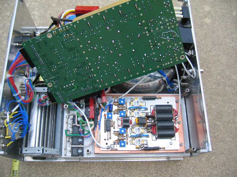
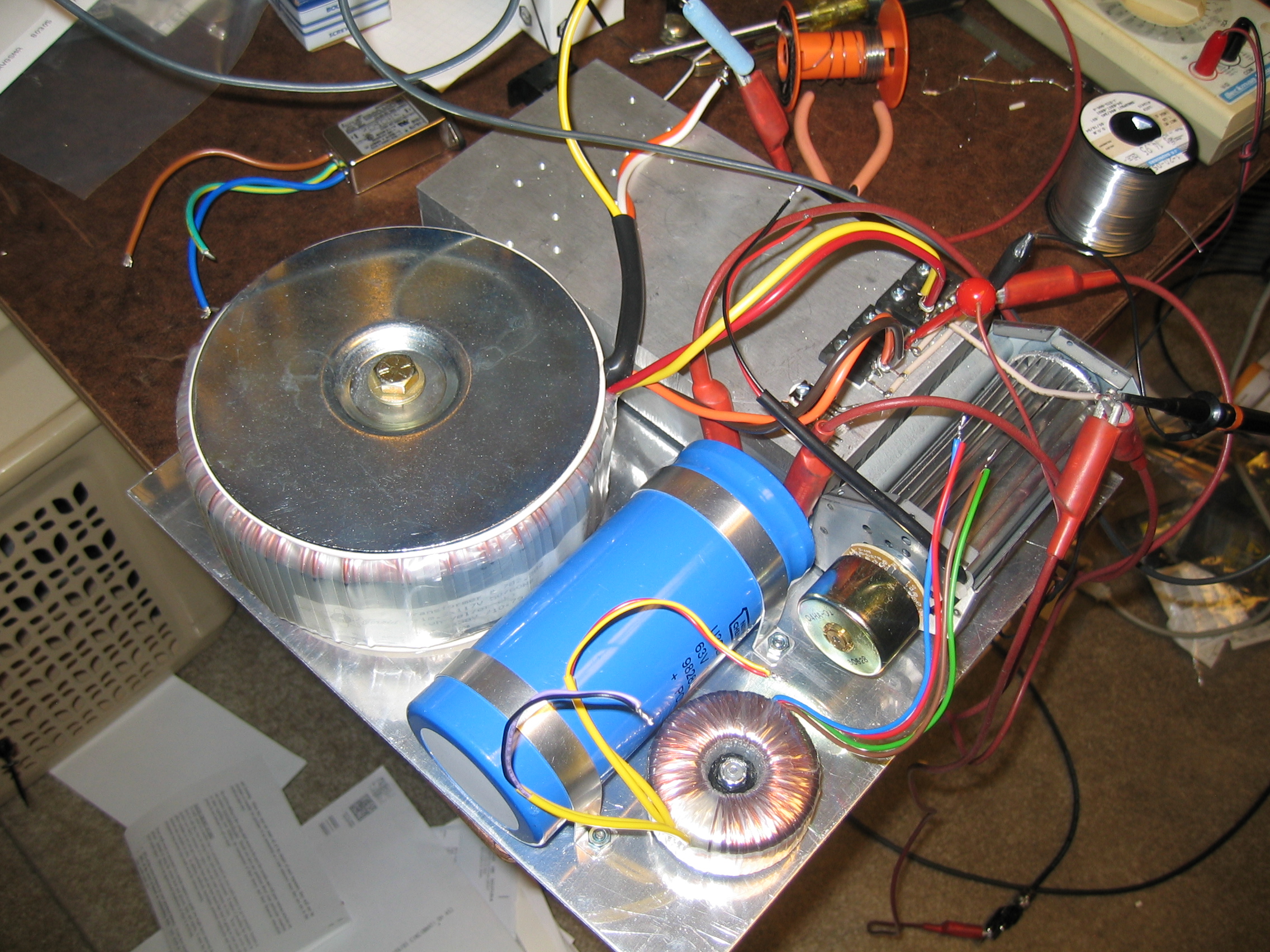
The power supply is a conventional capacitor input, non-regulated supply. The transformer delivers 38 VRMS at 22 Amps to a conventional bridge rectifier which feeds a 120,000 uFd capacitor rated at 63 volts. The resulting no load voltage is typically 53 volts. During average SSB operation this drops to about 50 volts. The transformer is a stock item from Toroid Corporation of Maryland. The specifications are listed for the following stock number 782.382. It sells for about $130.00.
The RF board is from Communication
Concepts. It is a Helge Granburg design that uses 4-MRF150's
in parallel pushpull. The circuit diagram and desccription is described
in application note EB-104. Pictures
A through G shown below show some of the construction process.
 E..HR..
 F...
F... G
G
Pictures A through Y below show various details of the construction.
All schematics that relate to the PC board are referenced to the Control
Board. The other schematics are self explanatory. If you download
the free ExpressPCB , the full
set of schematics may be viewed by downloading the .sch
file. The construction is such that the control board, rf module,
back panel, front panel, heat sink and main chassis all seperate and can
be unplugged from one another.
 E..HR..
 F..HR..
 G..........
 H..HR..
 Y..HR
Y..HR
The filters can be seen plainly in photos X and Y above. Since the amplifier runs in push-pull, the second harmonic is more than 40 db down without the filter and the third harmonic is about 15 db down. This eases the filter design so that only four filters are needed. These four filters are switched in automatically with my FT-857 or manually with the band switch. The inductors are airwound so there is no danger of core saturation. The unloaded Q of the inductors is about 200 which means the insertion loss is only a few tenths of a db. The theoretical response and return loss of each filter is shown below. The return loss is shown in red. The actual filters were quite close to theoretical. The SWR sampler is placed before the filters so that if a wrong filter is selected, a high SWR fault occurs and the amplifier is switched out of the circuit. Since the return loss in the pass band of the filters is about 16 db maximum resulting in a maximum SWR of 1.38:1, the reverse power meter will show a reading even if a 50-ohm dummy load is connected to the output. If an antenna tuner is used, this reflected power can be reduced which means that the amplifier is actually looking at 50 ohms at it's output ahead of the filters.

80 Meter Lowpass Filter

40/30 Meter Lowpass Filter

20/17 Meter Lowpass Filter

15/12/10 Meter Lowpass Filter
Photos A through C below show the initial testing. Each transistor was biased at 250 mA of quiescent current resulting in 3rd and 5th IMD products being 35 db down.
Finally, labels and a custom meter face were installed as shown in photos A and B below. The custom meter face was easy using a meter program from Tonne Software. You can try it out for a while and the cost is about $25.00.
The complete schematic is shown below. Greater details may be
had by clicking on each schematic.

Back Panel

Front Panel

Control Portion of Control Board

Filter Portion of Control Board

Auto Band Switching Portion
of Control Board

Control Circuits Mounted on
the Heat Sink
Results:
On-the-air tests have indicated that the amplifier is clean and linear.
Normal SSB transmission results in the heat sink temperature rising to
about 35 °C.


